| 일 | 월 | 화 | 수 | 목 | 금 | 토 |
|---|---|---|---|---|---|---|
| 1 | 2 | 3 | ||||
| 4 | 5 | 6 | 7 | 8 | 9 | 10 |
| 11 | 12 | 13 | 14 | 15 | 16 | 17 |
| 18 | 19 | 20 | 21 | 22 | 23 | 24 |
| 25 | 26 | 27 | 28 | 29 | 30 | 31 |
- 임베디드
- 8051
- easyeda
- TM4C123GXL
- bldc
- PCB
- Arm
- 전자공학
- TI
- 아트웍
- RTOS
- m4
- 임베디드시스템
- EMBEDDED
- Programming
- 7 세그먼트
- JLCPCB
- terminal
- CCS
- IoT
- Embedded System
- 모두의연구소
- St
- mcu
- GPIO
- 초보개발자
- MAC OS
- TM4C123
- Developer
- 마이컴
- Today
- Total
Engineering Agit
[8051 Micro-processor study 02] - #1 AT89S52 Pin description 본문
[8051 Micro-processor study 02] - #1 AT89S52 Pin description
Sean_Kim95 2020. 3. 1. 18:11
Vcc, GND, Port 0(P0.0~P0.7), Port1(P1.0~P1.7), Port2(P2.0~P2.7), Port3(P3.0~P3.7), RST, ALE/PROG, PSEN, EA/Vpp, XTAL1, XTAL2
1. Port 0 (P0.0~P0.7)
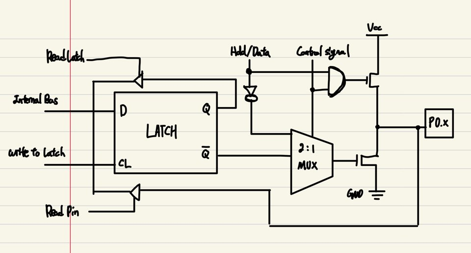
'Port 0'은 8bit open drain 양방향 I/O port이다. Output으로 사용되면, 각 pin은 8개의 TTL(Transistor-Transistor Logic) input을 sink할 수 있다. Port 0 pin에 1s를 쓰면 high impedence input pin으로 쓸 수 있다.
Port 0은 외부 program & data memory에 접근할 때 multiplexed low-order address/data bus로 사용할 수 있다. 이 모드에서 P0는 내부 풀업을 갖는다.
또한 flash programming중 일때 code byte를 받고 program verification중 일때 code byte를 내보낼 수 있다. Program verification중에는 외부 풀업이 필요하다.
2. Port 1 (P1.0~P1.7)
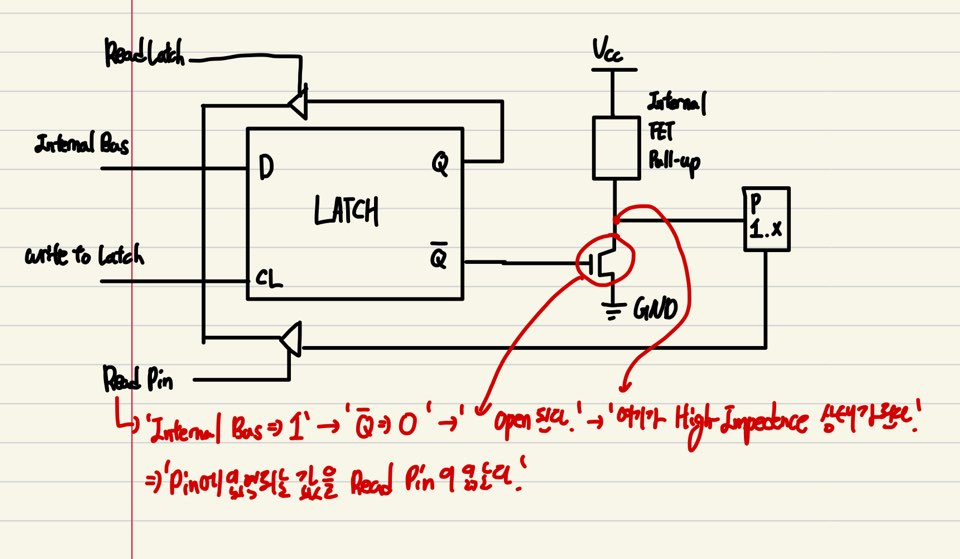
'Port 1'은 내부풀업을 갖는 8-bit 양방향 I/O port이다. Port 1의 output buffer는 4개의 TTL input으로 sink 또는 source할 수 있다. Port 0과 같이 pin에 1을 쓰면 input으로 사용가능하다. 'input'으로 사용할 때 port 1의 pin에 외부 풀다운이 걸려있다면, pin의 내부 풀업에 의해 전류(I_IL)을 내보낸다. 이는 마치 pin에서 high output을 내보내는 것과 같다. 이때의 전류량은 최대 15.0mA이다. 이는 I/O pin과 연결한 application에 따라 부족할 수 있으므로 pin에 0을 써서 전류의 sink로 사용하는 것이 좋다.

'Port 1' 또한 Flash programming과 verification 동안 low-order address bits를 받는다.
3. Port 2 (P2.0~P2.7)
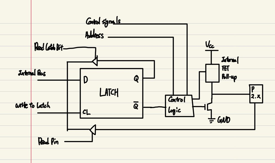
Port 2는 내부풀업을 갖는 8-bit 양방향 I/O port이다. Port 1의 output buffer는 4개의 TTL input으로 sink 또는 source할 수 있다. Port 0과 같이 pin에 1을 쓰면 input으로 사용가능하다. 'input'으로 사용할 때 port 1의 pin에 외부 풀다운이 걸려있다면, pin의 내부 풀업에 의해 전류(I_IL)을 내보낸다. 이는 Port 1과 동일하다.
Port 2는 external program memory에서 데이터를 fetch해 올 때나 16bit 주소값을 사용하는 external data memory(MOVX@DPTR)에 access할 때 high-order address byte를 내보낸다. 이런 application에서 port 2는 1을 내보낼 때 강한 내부풀업을 이용한다. 8bit 주소값을 사용하는 external data memory에 access할 때 port 2는 P2 SFR(Special fuction register)의 값을 내보낸다.
Port 2는 또한 Flash programming과 verification 시에 high-order address bit들과 몇 개의 control signal들을 받는다.
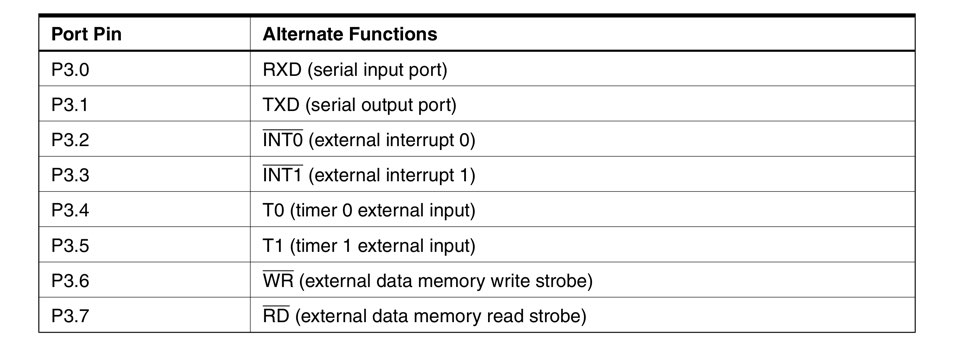
4. Port 3 (P3.0~P3.7)
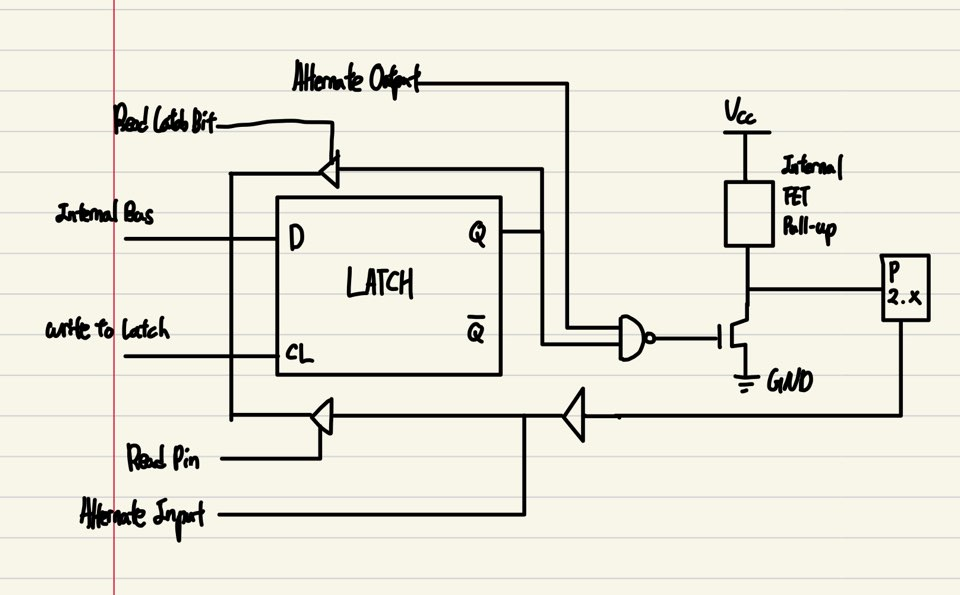
Port 3의 기본적인 특징은 port 1, 2와 같다.
Port 3는 Flash programming과 verification을 위한 몇 개의 control signal을 받는다.
Port 3는 또한 AT89S52의 여러 특별한 특징을 갖는 기능들을 수행한다.
5. RST
Reset input이다. Reset을 위해서는 oscillator가 동작하는 동안 2 machine cycles(12MHz의 경우 1us/1MC)동안 이 pin에 high를 주면 된다. 이 pin은 WATCHDOG times out 이후 98 oscillator periods 동안 high를 유지한다. SFR의 AUXR(주소: 0x8E)의 DISRTO bit는 이러한 기능을 사용하거나 사용하지 않게 할 수 있다(Default state에서 이 bit는 이 기능을 사용하게 설정되어있다).
6. ALE/PROG
ALE(Address Latch Enable)은 external memory에 access하는 동안 주소값의 low byte를 latching하기 위한 output pulse이다. 이 pin은 flash programming중에는 program pulse input이 된다.
일반적인 작동상태에서 ALE는 oscillator의 주파수의 1/6의 일정한 주기를 내보내며 이는 다른 장치의 외부 clock으로 이용될 수 있다. [주의! 이러한 목적으로 사용시에 만약 external data memory에 access한다면 각각의 access마다 ALE의 pulse하나가 사라진다.]
필요에 따라 SFR의 0x8E 번지에 ALE setting bit에 0을 씀으로써 비활성화할 수 있다. 이러한 bit set 이후에는 MOVX나 MOVC instruction 중에만 ALE가 활성화된다. 그 외에는 이 pin이 약하게 풀업된다. 이러한 setting은 uC가 external execution mode일 때는 효과가 없다.
7. PSEN
Program Store Enable(PSEN)은 external program memory를 읽을 지를 결정하는 strobe역할을 한다. AT89S52가 external program memory에서 code를 실행할 때, PSEN는 각 machine cycle에 2번 active되고 external data memory에 access할 때는 이 과정이 제외된다.
8. EA/VPP
External Access Enable이다. EA는 0x00에서 0xFFFF까지의 주소를 갖는 external program memory에서 code를 fetch하는 것을 활성화하기 위해 반드시 GND에 연결되어 있어야한다. [주의! 만약 lock bit에 1이 쓰여지면 이 pin은 내부적으로 reset에 latch되어질 것이다.]
EA는 장치가 internal program을 실행한다면 Vcc에 연결되어 있어야한다.
이 pin은 flash programming중에는 12V programming enable voltage(Vpp)를 받는다.
9. XTAL1
Inverting oscillator amplifier 혹은 internal clock operating circuit의 input이다.
10. XTAL2
Inverting oscillator amplifier의 output이다.
Reference
-AT89S52 datasheet, Prod. ATMEL corp., 2008


